
So, when I was working on this one I decided to took notes on my approach to debugging after stumbling upon a leaked boardview for this motherboard.
I bought this board in unknown condition and figured it was missing a CPU or had some messed up voltage regulation. Upon further testing I quickly realised all power rails checked out good and that the CPU wasn't initialising because the debug code on the board was stuck at 00 and as expected the board did not post.
After trying some more things out I discovered USB flashback was straight up failing which is unusual and indicated to me that there was some sort of SPI related fault, so I started taking a look at the bios chips and realised someone had resoldered those but must've done so by hand because they still had intact "1.40" lables.
Indeed, under those labels hid two completely different 16MB bios chips, a macronix branded part and a windbond branded one. After seeing this I decided to desolder them using hot air and externally flash them with known good dumps.
Unfortunately I had no luck with this but soon after finding bios dumps online I stumbled upon a boardview which would've helped me dig further.
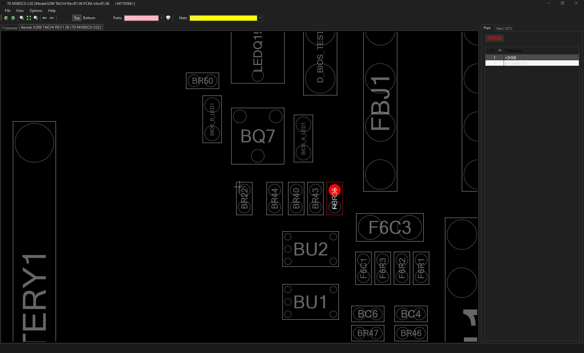
The first thing I noticed looking at the boardview was a UART debug header for the bios flashback IC.
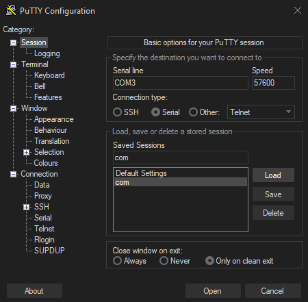
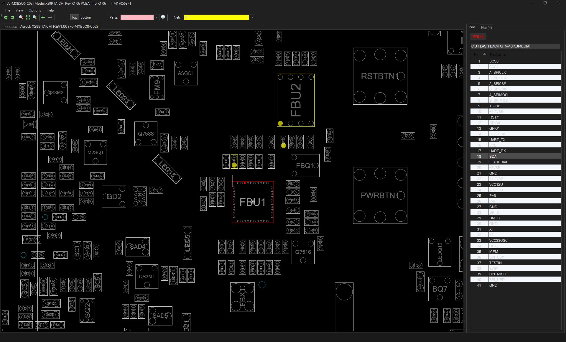
After quickly bridging over 3.3vsb to the header using some convenient unpopulated pads I could connect a USB to UART device and after some trial and error I got readable debug using 57600 baudrate. At this point I also noticed the part number listed on the boardview matched the macronix part and kept it in mind.

Now, with some useful debug for the bios flashback circuit I could run a flashback attempt with both chips while monitoring the output. after comparing my results I realised the only difference between them is the SPIROM ID which at least indicated towards a working chip select line. here's the pastebins for both outputs: https://pastebin.com/bh0vmAeL https://pastebin.com/58Hwe2U0
After a quick look the output seem too useful but the EEPROM data being wiped out weirded me out. I still didn't really know what the EEPROM was even for, maybe to store unique information like a MAC address? Who knows...
Out of desperation I even checked continuity between traces SPI traces and checked all pull ups, just in case
At this point I was unsure on how to go forward and I didn't see many debug other connectors to try and use so I decided to get some rest and ask around for more help.
The next day with a fresh mind looking at the boardview again I noticed some interesting things took a closer look at those
The first thing to catch my attention was that there wasn't just one SPI rail going straight from the PCH to the bios chip but instead all data was bridged over with the flashback chip which is an interesting approach to say the least...


After noticing this I started sketching out on the board view and reseaching into the SPI protocol to better understand the communication between devices. After taking some measurements, quite surprisingly it looked more like the SPI Master on the PCH side, so the PCH itself, wasn't working as intended so I started suspecting some minor rail went missing or some signal was causing it to halt.


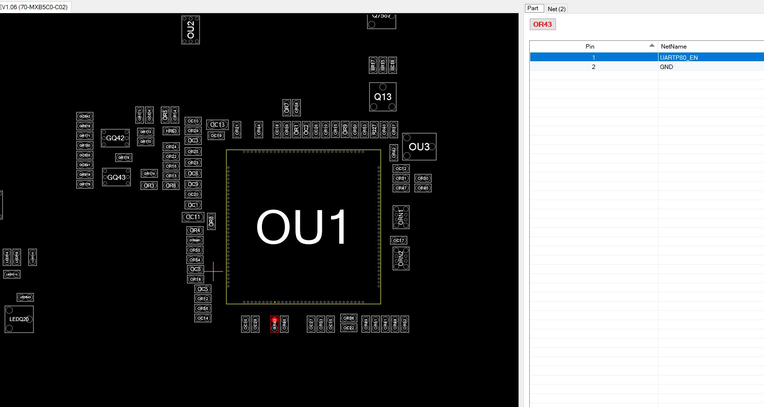
At this point I checked every possible power line to the PCH it all seemed to be right where it expected it to be so I moved onto the other discovery I had made, which was a UART header for the superio chip so I started working to get some kind of output from it.

Unfortunately, even after bridging enable lines to ground I couldn't get any UART output which made me suspect that it either got stuck very early in init or that some sort of voltage was missing somewhere
Out of desperation I started looking at linear regulators because I know all switching power supplies were up and running as expected since I probed all the inductors on the board and I noticed some regulators that weren't outputting anything around the cpu socket but figured they were fine since they're S3 rails so I figured those were fine.
At this point I started looking over at signals and I quickly noticed something very interesting, CPU_RESET# stays at VCCIO for a while, then the board resets and the CPU_RESET# signal stays low. This probably meant that the CPU only gets stuck in reset after something fails in early init
And this is where our little adventure ends, I've looked some more around the board to find the fault but I suspect either the PCH is toast or the EEPROM requires something specific programmed to it or that there's some broken data lane somewhere, unfortunately all PCH debug features are disabled on retail parts and it's probably not worth swapping over a PCH from a donor on this one. I would've tried porting coreboot to debug further, maybe even bypassing the flashback functionality completely but unfortunately there's no open source hardware bringup routine so I am out of luck for now on this one.
Well, first of all hopefully this gives an insight on my debugging techniques and highlights how much easier a boardview or schematic make debugging a problem like this, unfortunately you can't win them all... But hey! I've never had to deal with a bios flashback circuit before and I didn't even know the debug features were present, let alone left enabled...
here's your navigation buttons, as much as I find them silly.
Blog Index Main Page